A linear shaft motor is a type of direct-drive electric motor that produces linear motion directly — without gears, lead screws, timing belts, or any mechanical transmission. It converts electrical current into linear force (thrust) with nothing between the coil and the load.
Unlike rotary motors that require a rotary-to-linear conversion mechanism, a linear shaft motor moves in a straight line inherently. This fundamental simplicity eliminates mechanical transmission losses, backlash, wear, and the complexity of conversion mechanisms. The result is a motor system with precision, speed, and reliability that indirect-drive systems cannot match.
Nippon Pulse America's linear shaft motors use a unique cylindrical architecture — a permanently magnetized shaft that slides through a cylindrical copper coil assembly — making them different from flat-bed linear motors and giving them performance advantages that have made them the preferred choice for semiconductor, medical device, and precision automation applications worldwide.
How a Linear Shaft Motor Works
The operating principle of a linear shaft motor is a direct application of Lorentz's force law: a current-carrying conductor in a magnetic field experiences a force proportional to the current, the magnetic field strength, and the length of conductor in the field.
The two main components are:
- The shaft (magnetic track) — A precision-ground stainless steel or aluminum shaft with permanent magnets arranged in alternating poles along its length. This is the stationary element (though in some configurations it moves).
- The forcer (coil assembly) — A cylindrical assembly of copper coils wound around the shaft. This is the moving element attached to your load.
When three-phase AC current is applied to the coils in the forcer, a traveling electromagnetic field is created along the shaft axis. The interaction between this field and the permanent magnets in the shaft produces thrust — pushing or pulling the forcer along the shaft in a perfectly linear path.
By varying the current amplitude and phase, the motor controller can precisely control force, velocity, and position in real time. The shaft motor responds to commands in microseconds, with no mechanical delays from backlash or compliance.
The Cylindrical Difference: Why the Shape Matters
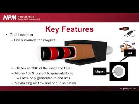
Most people first encounter linear motors in a flat-bed configuration — coils on one side, a flat magnetic track on the other. Linear shaft motors are fundamentally different: the magnets form a cylindrical shaft, and the coils surround it on all sides.
This cylindrical architecture produces three key engineering advantages:
1. True Zero Cogging Force
The coil assembly contains no ferromagnetic (iron) material — only copper and composite. Without iron, there is no magnetic attraction between the forcer and the shaft. This eliminates cogging force entirely: the parasitic position-dependent force that creates jerky motion in iron-core motors. Zero cogging means perfectly smooth motion at any speed.
2. 360° Electromagnetic Interaction
Because the coils completely surround the shaft, all of the magnetic flux generated by the permanent magnets participates in force production. A flat linear motor only uses one side of its magnetic track. The cylindrical motor uses all 360 degrees, making it approximately 50% more efficient for a given motor volume.
3. Self-Canceling Radial Forces
The cylindrical symmetry means magnetic attraction forces from the shaft's permanent magnets pull equally in all radial directions. They cancel out, leaving only useful axial thrust force. This means no net side-load on the bearings from the motor itself — extending bearing life and simplifying mechanical design.
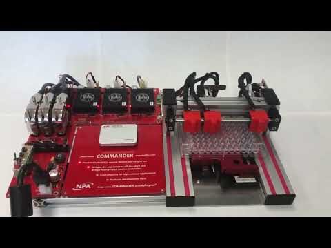
Key Components of a Linear Shaft Motor System
A complete linear shaft motor system consists of five main elements:
1. The Magnetic Shaft
Precision-ground shaft with alternating North-South permanent magnets. Available in various diameters (typically 16mm to 100mm) and lengths up to several meters. The shaft is the stationary element in most configurations and requires precise mounting at both ends.
2. The Forcer (Coil Assembly)
The moving element that your load attaches to. Contains multiple sets of three-phase copper coils wound in a cylindrical configuration around the shaft. The forcer slides freely along the shaft on its own internal bearings or on external linear guide bearings.
3. Linear Guides / Bearings
Unlike rotary motors, linear shaft motors do not provide their own radial stiffness — they produce only axial (linear) force. External linear guides or air bearings are required to constrain radial movement and carry side loads from the workpiece.
4. Linear Encoder
Precision position feedback is required for closed-loop servo control. Linear encoders with resolutions of 0.1 to 1 micron are typical. The encoder signal feeds the servo drive, closing the position control loop.
5. Servo Drive and Motion Controller
The servo drive (amplifier) provides the three-phase current to the forcer based on commands from a motion controller. Modern servo drives close the position loop at update rates of 10-100 kHz for precise tracking.
Linear Shaft Motor vs. Other Linear Motion Technologies
Engineers evaluating linear motion options typically compare four technologies:
| Technology | Mechanism | Max Speed | Precision | Maintenance |
|---|---|---|---|---|
| Linear Shaft Motor | Direct electromagnetic | 5+ m/s | Sub-micron | None (contactless) |
| Ball screw | Rotary → linear conversion | ~1 m/s | 1-5 µm | Regular lubrication |
| Flat linear motor | Direct electromagnetic | 5+ m/s | Sub-micron | Minimal |
| Pneumatic cylinder | Fluid pressure | ~2 m/s | ~0.5 mm | Regular |
The linear shaft motor's combination of sub-micron precision, high speed, zero maintenance, and zero cogging places it in a performance class that no other technology matches for demanding applications.
Common Applications
Linear shaft motors are found wherever precision, speed, or reliability requirements push beyond what traditional mechanical drives can deliver:
- Semiconductor equipment — Wafer handling, lithography stages, inspection systems, wire bonding machines
- Medical devices — Robotic surgery systems, diagnostic equipment, drug delivery systems, medical grippers
- Electronics assembly — Pick-and-place machines, soldering systems, board inspection equipment
- Metrology — Coordinate measuring machines, surface profilometers, optical inspection
- Optics and photonics — Laser systems, optical alignment stages, interferometry equipment
- Research and laboratory — Scanning microscopes, nanopositioning stages, materials testing
The common thread: these applications need precision that mechanical transmission systems cannot provide, speeds that pneumatics cannot control, or reliability that wear-based systems cannot sustain.
Is a Linear Shaft Motor Right for Your Application?
A linear shaft motor is likely the right choice if your application has one or more of these characteristics:
- Precision requirement below 5 micrometers — Ball screws struggle below this level due to backlash, lead error, and thermal effects
- High speed (above 1 m/s) — Ball screws face resonance, whip, and bearing speed limits above ~1 m/s
- High duty cycle or continuous motion — No wear means no degradation over time
- Cleanroom or vacuum environment — No lubrication required; no outgassing from grease or oil
- Long service life requirement — No mechanical wear; contact-free design lasts indefinitely
- Smooth motion at low velocity — Zero cogging means no stick-slip, even at sub-mm/s speeds
If your primary constraint is lowest initial cost and precision requirements are modest (>10 µm), a ball screw may be the more economical solution. But for any of the above requirements, linear shaft motors deliver performance that pays for themselves quickly in reduced maintenance, higher throughput, and better yield.
Conclusion
A linear shaft motor is the most direct path from electrical command to precise linear motion. By eliminating mechanical transmission entirely, it removes the sources of backlash, compliance, wear, and efficiency loss that limit all indirect-drive systems.
The cylindrical architecture adds a further advantage: zero cogging force, 360-degree magnetic coupling, and superior thermal management — all from a single elegant design principle.
For engineers designing systems where precision, speed, or long-term reliability matter, linear shaft motors represent the current state of the art in linear motion technology. Nippon Pulse America has been delivering these motors for demanding applications in semiconductor, medical, and industrial automation since 1952.