Cogging force—the magnetic attraction between a motor's permanent magnets and iron core—represents one of the most significant challenges in precision motion control. This parasitic force creates position-dependent resistance that manifests as jerky motion, velocity ripple, and positioning errors. For applications requiring nanometer-level precision or ultra-smooth velocity control, cogging is simply unacceptable.
Linear shaft motors eliminate cogging force entirely through a revolutionary ironless cylindrical design. Understanding the physics behind this achievement reveals why cylindrical linear shaft motors have become the preferred choice for the most demanding precision automation applications.
What is Cogging Force?
Cogging force, also called detent force, occurs when permanent magnets in a motor are attracted to the ferromagnetic (iron) material in the motor's stator or forcer. This magnetic attraction varies as the magnets move relative to the iron, creating a position-dependent force that opposes smooth motion.
In traditional linear motors with iron cores, the cogging force follows a sinusoidal pattern with peaks occurring when magnets align with iron teeth. The magnitude of cogging force depends on several factors:
- Magnet strength — Stronger magnets create higher cogging forces
- Air gap — Smaller gaps increase magnetic attraction and cogging
- Iron tooth geometry — Tooth width and spacing affect cogging frequency
- Slot/pole ratio — The relationship between magnet pitch and iron teeth
The cogging force can be expressed as:
F_cog = K * B * sin(n * θ)
Where:
- F_cog = Cogging force
- K = Cogging constant (depends on geometry and materials)
- B = Magnetic flux density
- n = Number of pole pairs
- θ = Position angle
For precision applications, even small cogging forces (1-2% of rated force) create unacceptable disturbances. At low velocities, cogging causes stick-slip motion. At higher speeds, it generates velocity ripple and vibration. Neither is acceptable for semiconductor lithography, medical imaging, or precision metrology.
The Iron-Core Problem
Traditional linear motors use iron cores in the forcer (moving coil assembly) for a compelling reason: iron dramatically increases magnetic flux density. When copper coils are wound around iron teeth, the high magnetic permeability of iron (μr ≈ 4000) concentrates magnetic flux, allowing the motor to generate more force from the same coil current.
However, this design creates an unavoidable problem: the permanent magnets in the track are powerfully attracted to the iron teeth in the forcer. As the forcer moves, this magnetic attraction varies periodically, creating cogging force.
Attempts to Reduce Cogging in Iron-Core Motors:
- Skewing magnets — Angling magnets slightly reduces peak cogging but doesn't eliminate it and decreases force output
- Optimizing slot/pole ratios — Careful selection can reduce cogging but never eliminates it
- Adding auxiliary poles — Increases complexity and cost with limited effectiveness
- Electronic compensation — Requires position-dependent force feedforward, adding control complexity
Despite decades of research, no iron-core linear motor design has achieved true zero cogging. The fundamental physics prevents it: where iron and magnets coexist, magnetic attraction is inevitable.
The Linear Shaft Motor Solution: Ironless Design
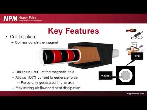
Linear shaft motors take a revolutionary approach: eliminate the iron core entirely. The forcer consists of copper coils wound in a cylindrical configuration with an epoxy or composite structure—no ferromagnetic material whatsoever.
Without iron in the forcer, there is nothing for the permanent magnets to be attracted to. The result is true zero cogging force—not "reduced" or "minimized," but completely eliminated.
Key Design Elements of Ironless Linear Shaft Motors:
- Copper-only forcer — Coils wound on non-magnetic former
- Cylindrical magnet shaft — Permanent magnets arranged around shaft circumference
- Air gap only — No magnetic material to vary gap reluctance
- Symmetric field — 360° electromagnetic interaction
The absence of iron means the magnetic flux density is lower compared to an iron-core motor (approximately 0.3-0.5 Tesla vs 0.8-1.2 Tesla). However, the cylindrical architecture compensates for this through two mechanisms:
1. 360° Electromagnetic Interaction
Unlike flat linear motors where coils interact with magnets on one side only, linear shaft motors surround the magnetic shaft completely. The entire circumference of coils contributes to force generation, effectively doubling the active electromagnetic surface area compared to a flat motor of equivalent size.
2. Balanced Radial Forces
The cylindrical symmetry means radial magnetic forces cancel out. All magnetic attraction forces from the permanent magnets pull equally in all radial directions, resulting in zero net radial force. Only axial force (thrust) remains—exactly what we want for linear motion.
Quantifying the Advantage: Zero Means Zero
When we say linear shaft motors have "zero" cogging, we mean it literally. Measurements show cogging force below the noise floor of even high-resolution force sensors (< 0.001% of rated force).
Compare this to "low-cogging" iron-core linear motors:
| Motor Type | Typical Cogging Force | Impact on Precision |
|---|---|---|
| Standard iron-core linear motor | 5-10% of rated force | Severe velocity ripple, stick-slip at low speed |
| "Low-cogging" iron-core motor | 1-2% of rated force | Improved but still measurable ripple |
| Linear shaft motor (ironless) | < 0.001% of rated force | No measurable cogging, true smooth motion |
This dramatic difference is visible in real-world performance:
- Velocity ripple — Linear shaft motors maintain constant velocity within encoder resolution limits
- Following error — Position tracking remains within servo loop resolution
- Low-speed smoothness — No stick-slip motion even at sub-millimeter/second velocities
- Force consistency — Generated force depends only on coil current, not position
Application Impact: Where Zero Cogging Matters
Zero cogging force isn't just a technical specification—it enables applications that are impossible with iron-core motors:
Semiconductor Lithography and Inspection
Wafer stages require nanometer-level positioning accuracy with absolutely no force disturbances. Even 0.5% cogging force would create unacceptable vibration and positioning errors. Linear shaft motors' zero cogging enables the smooth, precise motion required for sub-10nm lithography nodes.
Medical Imaging
CT scanners, PET scanners, and linear accelerators require perfectly smooth motion to prevent image artifacts. Any velocity ripple translates directly to image quality degradation. Linear shaft motors deliver vibration-free motion for diagnostic accuracy.
Metrology and Coordinate Measuring Machines
High-precision measurement systems need smooth motion without force disturbances that could affect measurement accuracy. Cogging force creates measurement errors and reduces repeatability. Zero cogging ensures measurement integrity.
Laser Processing and Cutting
Laser systems require perfectly smooth motion to maintain consistent beam delivery. Velocity ripple from cogging creates surface finish variations and cut quality problems. Linear shaft motors ensure uniform laser processing.
Pick-and-Place with Fragile Components
Handling delicate electronic components, medical devices, or glass substrates requires smooth acceleration without jerky motion. Cogging force can damage sensitive parts. Zero cogging enables gentle, precise handling.
The Trade-off: Why Not All Motors Are Ironless?
If ironless design eliminates cogging, why do iron-core motors still exist? The answer lies in force density and cost.
Iron-core motors generate approximately 2-3x more force per unit volume due to higher magnetic flux density. For applications where force capacity is critical and cogging is tolerable (or can be compensated), iron-core designs may be preferred.
However, linear shaft motors overcome this apparent disadvantage through their cylindrical architecture. The 360° electromagnetic interaction and superior efficiency mean that linear shaft motors often match or exceed the force output of similarly-sized flat iron-core motors—while maintaining zero cogging.
Additionally, linear shaft motors offer benefits beyond zero cogging:
- No attractive force — Ironless design means no magnetic attraction to the track, simplifying bearing loads
- Symmetric air gap — Cylindrical design is more forgiving of air gap variations
- Superior thermal management — Better heat dissipation from cylindrical geometry
- Longer mechanical life — No iron to fatigue or demagnetize adjacent magnets
Conclusion
The physics are unambiguous: iron + magnets = cogging force. By eliminating iron from the forcer design, linear shaft motors achieve true zero cogging—not an approximation, but a fundamental absence of magnetic attraction forces.
This isn't merely a performance improvement; it's a qualitative difference that enables new applications and sets new standards for motion precision. For any application where smooth motion, precision positioning, or vibration elimination is critical, the ironless cylindrical design of linear shaft motors provides an unmatched solution.
The next time you hear claims of "reduced cogging" or "low-cogging" motors, remember: only ironless linear shaft motors deliver true zero cogging force through fundamental electromagnetic design principles.