When specifying a direct-drive linear motor for precision automation, engineers face a fundamental architecture decision: cylindrical (linear shaft motor) or flat? Both eliminate the mechanical transmission components of traditional ball screw and belt drive systems, but they achieve direct drive through dramatically different electromagnetic architectures.
This analysis compares cylindrical linear shaft motors and flat linear motors across key engineering metrics—force density, efficiency, thermal performance, precision, and cost—to help engineers make informed decisions based on application requirements.
Architectural Fundamentals
Flat Linear Motors
Flat linear motors consist of a flat magnet track (typically permanent magnets mounted to a steel backing plate) and a forcer (coil assembly) that travels along the track. The forcer may be ironless (coreless) or iron-core. The electromagnetic interaction occurs across a planar air gap between the forcer and magnet track.
Key characteristics:
- Forcer travels along one side of magnet track
- Magnetic interaction on one surface only
- Requires precision-ground mounting surface
- Strong attraction force between forcer and track (in iron-core designs)
- Track can be easily extended to any length
Cylindrical Linear Shaft Motors
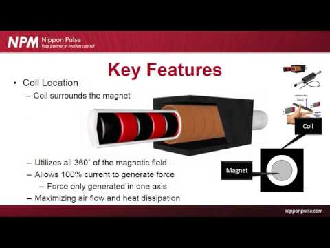
Linear shaft motors use a cylindrical magnetic shaft (permanent magnets arranged around a tubular core) and a tubular forcer that surrounds the shaft. The forcer consists of copper coils wound around a non-magnetic former in a cylindrical configuration. The electromagnetic interaction occurs across a radial air gap around the full 360° circumference.
Key characteristics:
- Forcer completely surrounds magnetic shaft
- Magnetic interaction across full 360° circumference
- Shaft supported by precision bearings at ends
- Zero net radial force (forces balance radially)
- Standard shaft lengths with optional extensions
Force Density and Output Capability
Peak Force Comparison
Iron-core flat linear motors achieve the highest peak force per unit volume due to high magnetic flux density (0.8-1.2 Tesla). The iron core concentrates magnetic flux, enabling very high force output from compact packages.
Typical peak force densities:
- Iron-core flat motor: 40-60 N/cm² of active area
- Ironless flat motor: 15-25 N/cm² of active area
- Cylindrical linear shaft motor: 25-40 N/cm² of active circumferential area
While iron-core flat motors show an apparent advantage in peak force density, this comparison is misleading for several reasons:
1. Active Area Geometry
Cylindrical motors have active electromagnetic surface area around the entire circumference. A 32mm diameter shaft has approximately 100mm of circumferential length—double the active surface of a 50mm wide flat motor track, despite similar cross-sectional envelope.
2. Continuous vs Peak Force
Continuous force rating (limited by thermal dissipation) is often more important than peak force in real applications. Here, cylindrical motors excel due to superior thermal management (discussed below). The continuous-to-peak force ratio is typically 50-60% for linear shaft motors versus 30-40% for flat motors.
3. System-Level Force
When comparing complete motion systems (motor + mounting + bearings), cylindrical linear shaft motors often match or exceed flat motor systems in usable force within similar envelope constraints, particularly for continuous duty applications.
Efficiency and Energy Consumption
As detailed in our article "Why Linear Shaft Motors Are 50% More Efficient," cylindrical motors demonstrate significant efficiency advantages over flat motors.
Efficiency Comparison:
| Motor Type | Typical Efficiency | Force Constant (Kf) | Key Loss Mechanisms |
|---|---|---|---|
| Iron-core flat motor | 70-80% | 15-25 N/A | Copper losses + Iron losses + Eddy currents |
| Ironless flat motor | 85-90% | 20-35 N/A | Copper losses only |
| Cylindrical linear shaft motor | 90-95% | 35-55 N/A | Copper losses only (optimally distributed) |
The efficiency advantage of linear shaft motors stems from:
- 360° flux utilization — All magnetic field participates in force generation
- Optimized copper distribution — Cylindrical geometry allows efficient winding
- Zero iron losses — Ironless design (shared with ironless flat motors)
- Balanced electromagnetic forces — No wasted energy in radial attraction
For high-duty-cycle applications, the 10-15% efficiency advantage translates directly to reduced operating costs, smaller power supplies, and lower thermal management requirements.
Thermal Management and Continuous Force
Thermal performance often determines the practical usability of a linear motor. Peak force specifications are meaningless if the motor overheats during continuous operation.
Cylindrical Linear Shaft Motor Thermal Advantages:
1. 360° Heat Dissipation Surface
The cylindrical forcer dissipates heat radially in all directions. The entire outer circumference serves as a heat dissipation surface. Compare this to a flat motor where heat primarily dissipates from one surface (the back of the coil assembly).
Heat dissipation surface area for equivalent motor volumes:
- Flat motor (50mm wide × 80mm long × 25mm thick): Effective cooling surface ≈ 4,000 mm²
- Cylindrical motor (32mm diameter × 80mm long): Outer cooling surface ≈ 8,000 mm²
The cylindrical motor has approximately 2× the heat dissipation surface area for similar volume, enabling better continuous force ratings.
2. Uniform Temperature Distribution
Cylindrical symmetry promotes uniform temperature distribution. There are no "hot spots" or thermal gradients that limit continuous force. Flat motors often show temperature variations between center and edges of the forcer.
3. Easier Liquid Cooling Integration
The cylindrical geometry naturally accommodates liquid cooling jackets. Many high-performance linear shaft motors incorporate water cooling channels in the outer housing for demanding applications. This is more challenging with flat motor geometries.
Practical Impact on Continuous Force:
For a typical application requiring sustained force:
- Iron-core flat motor: 600N peak, 200N continuous (33% duty)
- Ironless flat motor: 400N peak, 180N continuous (45% duty)
- Cylindrical linear shaft motor: 450N peak, 270N continuous (60% duty)
The linear shaft motor delivers 35% more continuous force than the ironless flat motor and 50% more than the comparable iron-core design.
Precision and Cogging Characteristics
Cogging Force Comparison:
- Iron-core flat motor: 1-10% cogging force (position-dependent)
- Ironless flat motor: Zero cogging (no iron core)
- Cylindrical linear shaft motor: Zero cogging (ironless design)
Both ironless architectures (flat and cylindrical) achieve zero cogging. However, cylindrical linear shaft motors have an additional precision advantage:
Symmetric Air Gap Tolerance
Flat motors are sensitive to air gap variations, tilt, and yaw. Any deviation from parallel alignment between forcer and track affects force output and can introduce force variations. The typical air gap tolerance is ±0.1mm.
Cylindrical motors have radially symmetric air gaps. Small variations in concentricity (±0.2mm) have minimal impact on force output because forces balance around the circumference. This makes cylindrical motors more forgiving during installation and operation.
No Attractive Force
Iron-core flat motors generate strong attractive forces (often 5-10× the motor thrust force) between forcer and track. This attraction force loads the bearing system and can cause bearing wear. It also makes installation more difficult.
Ironless flat motors have reduced attraction (typically 0.5-2× thrust force) but still present some magnetic preload.
Cylindrical linear shaft motors have balanced radial forces that cancel out. Net radial force is effectively zero, simplifying bearing selection and extending bearing life.
Installation and Integration Considerations
Flat Linear Motors — Installation Challenges:
- Requires precision-ground mounting surface (flatness < 0.05mm per meter)
- Track sections must align precisely (cumulative tolerance issues on long tracks)
- Air gap must be maintained across entire length
- Magnetic attraction requires robust mounting
- Cable management for long travels can be complex
Advantages:
- Unlimited travel length (just extend the track)
- Multiple forcers can travel on single track (though rarely practical)
- Low profile (thin envelope)
Cylindrical Linear Shaft Motors — Installation Characteristics:
- Shaft requires support bearings at ends (or center support for long strokes)
- Standard stroke lengths with optional shaft extensions
- Simpler mounting (less critical surface prep)
- Compact cylindrical envelope
- Integrated bearing options available
Advantages:
- Complete integrated motion axis (motor + bearings + encoder in single assembly)
- Simpler cable management (cables connect to stationary housing)
- More forgiving of mounting tolerances
- Cleaner aesthetic (all components enclosed)
Application Suitability Matrix
Choose Flat Linear Motors When:
- Very long travel lengths required (>2 meters) — Track can be extended indefinitely
- Ultra-thin profile needed — Flat motors can be very low profile
- Peak force is critical, duty cycle is low — Iron-core flat motors excel at peak force
- Horizontal axis with gravity load — Easier to support heavy loads on flat track
- Multiple independent movers on single track — Flat architecture supports this (though complex)
Choose Cylindrical Linear Shaft Motors When:
- High continuous force required — Superior thermal management enables sustained force
- Energy efficiency is critical — 50% better efficiency reduces operating costs
- Zero cogging essential, clean room required — Ironless design, sealed options
- Compact installation space — Cylindrical package can be very space-efficient
- High duty cycle or 24/7 operation — Efficiency and thermal advantages critical
- Simplified installation preferred — Integrated bearing options, less critical mounting
- Vertical axis applications — Balanced radial forces, no side loads
- Harsh environments — Sealed cylindrical designs available
Conclusion
Both flat linear motors and cylindrical linear shaft motors represent sophisticated direct-drive solutions that eliminate mechanical transmissions. The choice between them isn't about "better" or "worse"—it's about matching motor architecture to application requirements.
Flat linear motors excel in very long travel applications and where ultra-thin profiles are required. Iron-core flat motors offer the highest peak force density for intermittent duty applications.
Cylindrical linear shaft motors shine in continuous force applications, high duty cycle systems, and where energy efficiency matters. Their 50% efficiency advantage, superior thermal management, zero cogging, and balanced force characteristics make them ideal for precision automation in semiconductor, medical, metrology, and advanced manufacturing applications.
For most precision motion control applications with strokes under 2 meters, continuous operation, and strict efficiency or thermal requirements, cylindrical linear shaft motors offer compelling advantages that justify their specification.