Peak force specifications dominate motor datasheets, but continuous force determines real-world performance. A motor rated for 1000N peak force is useless if thermal limitations restrict continuous operation to 300N. Thermal management—the ability to dissipate heat generated by copper losses—often becomes the limiting factor in motor performance.
Linear shaft motors achieve superior thermal performance compared to flat linear motors through their cylindrical geometry. Understanding the heat transfer physics explains why cylindrical motors deliver 50-80% higher continuous force ratings and operate cooler in high duty cycle applications.
Heat Generation in Linear Motors
All electric motors generate heat primarily through resistive losses in the copper windings (I²R losses):
P_heat = I² × R
Where:
- P_heat = Heat generated (Watts)
- I = Current through windings (Amps)
- R = Winding resistance (Ohms)
Since force is proportional to current (F = Kf × I), generating force inherently generates heat. The question becomes: how efficiently can the motor dissipate this heat to maintain safe operating temperatures?
Thermal Limits:
Motor windings have maximum temperature ratings based on insulation class:
- Class F insulation: 155°C continuous
- Class H insulation: 180°C continuous
Exceeding these temperatures degrades insulation, risking short circuits and motor failure. Additionally, permanent magnets (NdFeB) lose magnetization above their Curie temperature (typically 80-150°C depending on grade).
The thermal design challenge is maximizing heat dissipation to keep both windings and magnets within safe operating temperatures.
Heat Transfer Fundamentals
Heat dissipation from motors occurs through three mechanisms:
1. Conduction
Heat flows from hot windings through motor structure to mounting surfaces. The rate depends on thermal conductivity and conduction path geometry.
Q_cond = k × A × ΔT / d
Where k = thermal conductivity, A = cross-sectional area, ΔT = temperature difference, d = conduction distance
2. Convection
Heat transfers from motor surfaces to surrounding air (natural or forced). This is typically the dominant heat transfer mode in air-cooled motors.
Q_conv = h × A × ΔT
Where h = convection coefficient (depends on air flow), A = surface area, ΔT = temperature difference between surface and air
3. Radiation
Heat radiates from surfaces as electromagnetic radiation. Usually minor for motor temperatures but increases with T⁴.
For most air-cooled linear motors, convection dominates. The key parameters become:
- Surface area (A) — More surface area = more heat dissipation
- Convection coefficient (h) — Improved by air flow (fans) or liquid cooling
Cylindrical Geometry Advantages
Linear shaft motors leverage cylindrical geometry for superior heat dissipation:
1. Maximum Surface Area to Volume Ratio
For a given motor volume, cylindrical geometry provides more external surface area than flat rectangular geometry.
Example comparison for equivalent motor volumes (160 cm³):
Flat motor: 50mm wide × 80mm long × 40mm thick
- External surface area: 2×(50×80) + 2×(50×40) + 2×(80×40) = 18,400 mm²
- Effective cooling surface (excluding mounting face): ~14,000 mm²
Cylindrical motor: 40mm diameter × 80mm long
- External surface area: π×D×L + 2×(π×D²/4) = π×40×80 + 2×(π×20²) = 12,566 mm²
- Effective cooling surface: ~12,566 mm² (full circumference cools)
While the absolute surface area is similar, the effective cooling geometry differs dramatically:
Flat Motor Cooling Limitations:
- Bottom surface mounted to track/structure (no cooling)
- Top and sides cool via natural convection
- Heat must conduct through thickness to reach cooling surfaces
- Temperature gradients from center to edges
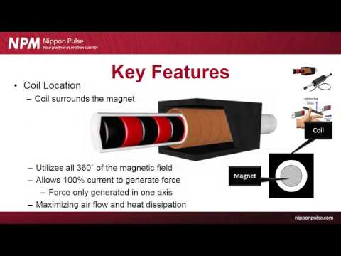
Cylindrical Motor Cooling Advantages:
- Full 360° outer circumference cools via convection
- Radial heat flow path is short (half the diameter)
- Symmetric cooling eliminates thermal gradients
- Natural chimney effect promotes air flow around cylinder
2. Shorter Thermal Conduction Path
In cylindrical motors, heat flows radially outward from windings to the outer cooling surface. The conduction distance is approximately:
d_radial = (D_outer - D_inner) / 2 ≈ 10-20mm
In flat motors, heat must conduct through the full thickness of the forcer (often 30-50mm) to reach the primary cooling surface.
Shorter conduction path = lower thermal resistance = cooler windings for same heat dissipation.
Continuous Force Comparison
The thermal advantages translate directly to higher continuous force ratings:
| Motor Type | Peak Force | Continuous Force | Duty Cycle | Thermal Time Constant |
|---|---|---|---|---|
| Iron-core flat motor | 1000N | 300N | 30% | 120 seconds |
| Ironless flat motor | 600N | 270N | 45% | 180 seconds |
| Cylindrical linear shaft motor | 700N | 420N | 60% | 240 seconds |
Key observations:
- Cylindrical motor delivers 40-55% higher continuous force
- Better duty cycle capability (60% vs 30-45%)
- Longer thermal time constant (slower temperature rise) provides better thermal margin
Practical Example:
For a pick-and-place application requiring 350N force:
- Iron-core flat motor: Exceeds continuous rating (300N), requires oversizing or active cooling
- Ironless flat motor: Exceeds continuous rating (270N), requires oversizing or cooling
- Cylindrical linear shaft motor: Within continuous rating (420N), no oversizing or cooling needed
The cylindrical motor runs cooler, more reliably, and at lower cost (no forced cooling required).
Enhanced Cooling Strategies
When applications demand even higher continuous force, cylindrical geometry naturally accommodates enhanced cooling:
1. Forced Air Cooling
Adding a fan to blow air across the motor surface increases the convection coefficient (h) by 3-5×:
- Natural convection: h ≈ 5-10 W/(m²·K)
- Forced convection: h ≈ 25-50 W/(m²·K)
The cylindrical outer surface naturally directs air flow around the circumference, maximizing cooling effect. Flat motors have dead zones where air flow is restricted.
2. Liquid Cooling Jackets
High-performance cylindrical motors incorporate liquid cooling channels in the outer housing. Water or coolant flows through channels surrounding the motor, dramatically increasing heat dissipation:
- Water cooling: h ≈ 500-2000 W/(m²·K) (50-100× better than air)
- Enables continuous force ratings approaching peak force (80-90% duty cycle)
- Maintains consistent temperature regardless of ambient conditions
The cylindrical geometry naturally accommodates annular cooling channels around the motor circumference. This is geometrically challenging with flat motors.
3. Heat Pipe Integration
Some advanced cylindrical motors integrate heat pipes in the outer housing to transfer heat away from the motor to remote heat sinks. Heat pipes provide effective thermal conductivity 100-1000× better than copper.
Temperature Distribution and Reliability
Beyond absolute thermal capacity, cylindrical motors provide more uniform temperature distribution:
Flat Motor Temperature Profile:
- Hot spot at center of winding (furthest from cooling surfaces)
- Cooler at edges near cooling surfaces
- Thermal gradients of 20-40°C from center to edge
- Thermal expansion creates mechanical stress
- Non-uniform magnet demagnetization risk
Cylindrical Motor Temperature Profile:
- Radially symmetric temperature distribution
- Minimal temperature variation (< 10°C) around circumference
- Uniform thermal expansion (no mechanical stress)
- Uniform magnet temperature (predictable performance)
Reliability Impact:
Temperature cycling and gradients stress motor components:
- Insulation fatigue: Repeated thermal cycling degrades insulation faster in presence of thermal gradients
- Magnet demagnetization: Non-uniform magnet temperatures cause uneven demagnetization, affecting force output
- Epoxy delamination: Thermal stress at material interfaces can cause potting compound failure
- Mechanical alignment: Thermal gradients cause distortion affecting air gap
The uniform temperature distribution in cylindrical motors reduces these stress mechanisms, extending motor lifetime.
Conclusion
Thermal management isn't a secondary consideration—it determines the usable performance of linear motors in real applications. Peak force specifications are meaningless if thermal limitations prevent sustained operation at required force levels.
Cylindrical linear shaft motors achieve superior thermal performance through fundamental geometric advantages: 360° cooling surface, short radial heat conduction paths, and symmetric temperature distribution. These translate to 50-80% higher continuous force ratings compared to flat linear motors.
For high duty cycle applications, continuous operation, or thermally-demanding environments, the thermal advantages of cylindrical linear shaft motors often justify their selection over flat motor alternatives. The motor that runs cooler lasts longer, performs more consistently, and requires less auxiliary cooling—critical factors for reliable automation systems.